PLATFORM FIELD GUIDE
Gen 3 RFSoC evaluation platform
ZCU216 field guide.
The ZCU216 is AMD's flagship evaluation platform for the Gen 3 Zynq UltraScale+ RFSoC: sixteen RF-ADCs and sixteen RF-DACs around a large programmable-logic fabric. It is the board RF and comms teams reach for when the question is "can we digitize at RF and process it in one device?" This guide covers what's on it, where bring-up time actually goes, and how to move it from the bench into a rack.
AT A GLANCE
At a glance.
- DEVICE
- Zynq UltraScale+ RFSoC ZU49DR (Gen 3)
- RF-ADC
- 16 channels · 14-bit · 2.5 GSPS
- RF-DAC
- 16 channels · 14-bit · 9.85 GSPS
- RF INPUT RANGE
- Direct RF to 6 GHz (Gen 3)
- CLOCKING
- CLK104 module · LMK04828 + LMX2594
- RF I/O
- XM655 breakout carrier, balun banks
- PROCESSING SYSTEM
- Quad-core Cortex-A53 + dual-core R5F
ARCHITECTURE
Architecture in brief.
The ZU49DR pairs the RF data converter tiles with a full UltraScale+ PL fabric and an ARM processing system. Converter tiles connect to the fabric through AXI4-Stream interfaces wide enough to carry full-rate samples, and each ADC tile carries hardened signal conditioning: fine-frequency NCO mixers, DDC decimation, and embedded calibration.
What makes the evaluation kit specifically useful is the clocking and RF plumbing around the device: the CLK104 daughter module provides the low-jitter sample clocks and the LMK04828-distributed references that multi-tile synchronization depends on, and the XM655 carrier breaks all thirty-two converter channels out to baluns and connectors. That is also where most integration surprises live.
BRING-UP
Bring-up: where the time goes.
01
Clock tree before everything
The CLK104's LMK04828 and LMX2594 must be programmed and locked in the right order before the RF tiles will start. Reference selection, PLL loop configuration, and lock verification are step zero. Symptoms of a wrong clock tree (tiles that won't power up, shutdown states, drifting captures) rarely point back at the clock.
02
RFDC configuration is a design decision
Tile and slice enablement, decimation settings, NCO frequencies, and interface widths interact with your fabric design's clocking and data-path width. Treat the RF Data Converter wizard's output as an architecture artifact to review, not a checkbox.
03
Multi-tile synchronization (MTS)
Coherence across tiles requires the MTS procedure: SYSREF capture, tile latency measurement, and alignment, every time the design initializes. Reference distribution quality on the CLK104 sets whether MTS converges repeatably. Budget verification time per element, not per board.
04
The analog edges
XM655 balun banks have pass-bands; DAC output power and ADC input scaling need to line up with your front end; and a bench setup that worked single-channel can degrade when all sixteen ADCs run; power and thermal margins are real at full tilt.
DEPLOYMENT
Racking it.
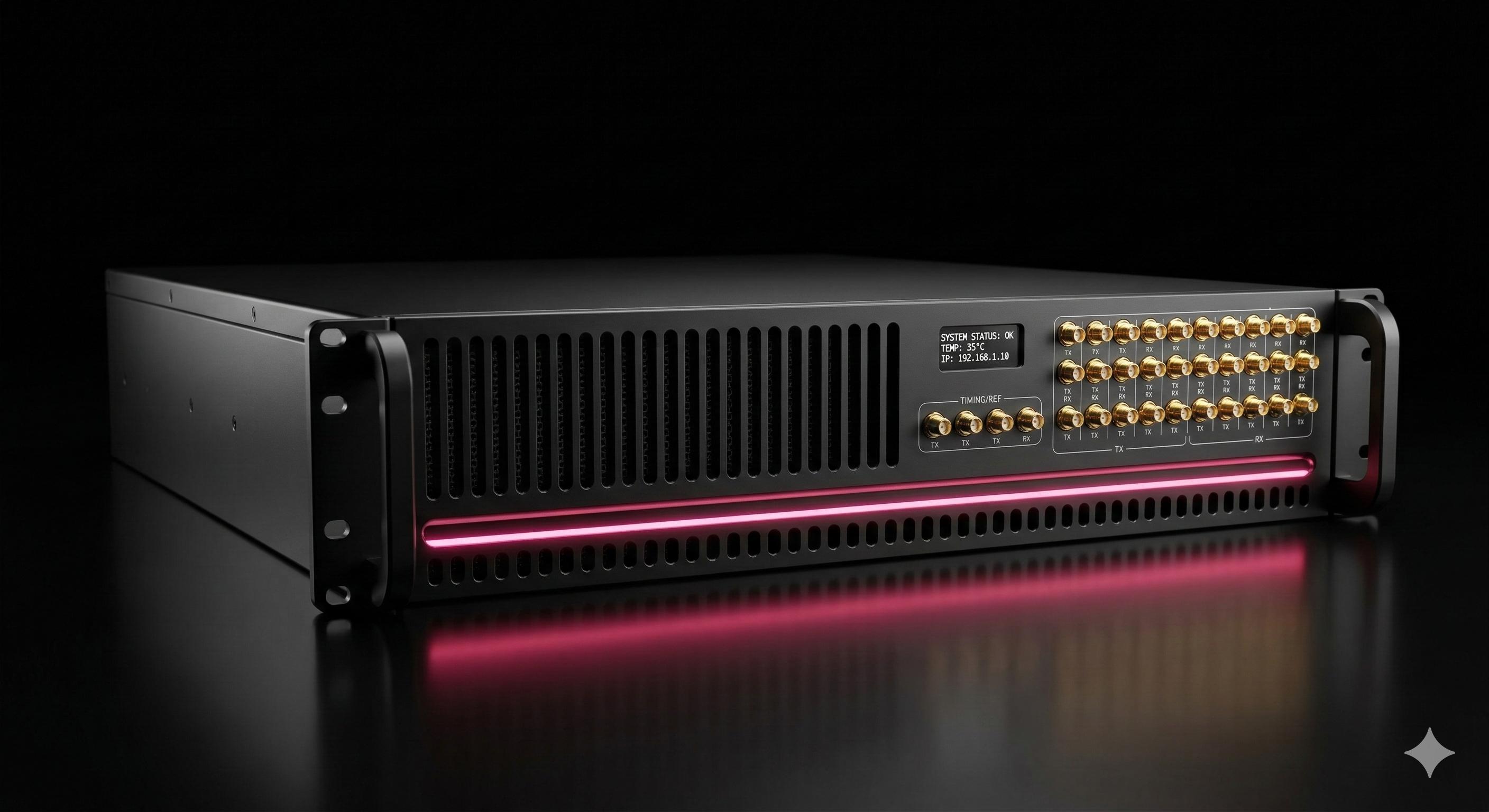
ZCU216 Enclosure
The evaluation kit is an open board with a bench power brick: fine for the lab, wrong for a rack. Our 2U rackmount enclosure gives the ZCU216 integrated thermal management, front-panel RF access, and tool-less installation, so the platform your firmware was proven on is the platform you deploy.
BUILDING ON IT
Building on it.
The DSP work on a ZCU216 is where Apexia lives: polyphase channelization and digital down-conversion cores delivered with simulation harnesses, plus MTS-aware multi-channel ingest reference designs for coherent capture.
The board is also a first-class CASPER toolflow target. Our CASPER integration service covers bitstream generation, custom yellow blocks, and hybrid CASPER/Vivado flows on ZCU216.
FROM THE BLOG
Further reading.
RFSoC BRING-UP AND DEPLOYMENT
Running aZCU216program?
PALM BAY, FLORIDA · 28.0345° N 80.5887° W
CLARITY BEYOND THE NOISE