FOUNDER DIARY · CHAPTER 01 / 10
The Itch: Why I Started Building Fabric
Chapter 1 of the Apexia founder diary: a folder of RFSoC scripts, a frequency plan nobody could see, and the idea that became Apexia Fabric.
- PUBLISHED
- OCTOBER 20, 2026
- READ
- 4 MIN READ
- BY
- THE FOUNDER · APEXIA
This is the first entry in a ten-part diary about building Apexia Fabric, a visual design tool for RFSoC and SDR signal chains, from the first commit to the version shipping today. It is written for engineers and founders who want to see how an idea turns into a minimum viable product and then into something people can install. Every date, version and count in this series comes from the project's own history. Where I explain a decision, I will say why it made sense at the time, not dress it up as a scene.
Chapter 1 covers the time before the first commit on April 7, 2026. It is about the itch: the problem that was annoying enough to build a product around.
A folder of tools that did not talk to each other
Before Fabric existed, I had a folder. In it were live spectrum viewers and IQ recorders for the RF data converter on a ZCU216, written in Python with PyQt; RF data converter test scripts; and BladeRF capture and DSP notebooks. Each one did its own job. None of them knew about the others, and none of them knew anything about the design they were measuring.
That last part is the important one. A spectrum viewer shows you what came out of the converter. It does not tell you what should have come out, given the sample rate, the Nyquist zone, the mixer setting and the decimation you chose. That comparison lived in my head.
Where the friction was
The CASPER toolflow (Hickish et al. 2016) is a well-trodden path; bringing an RFSoC board up through it still takes a lot of steps. Some are one-time chores: on the ZCU216, that meant fixing the board's MAC address in its EEPROM from the U-Boot prompt so it gets a stable link-local IP, then pinning a static IPv4 route on the host. Others recur: matching the MATLAB, Python and Vivado versions the toolflow expects, and block-design generation issues.
None of that is unusual, and none of it was the real problem. The real problem was that the configuration which decides whether a design works (which tiles and slices are enabled, the decimation factor, the NCO frequency, the Nyquist zone, the mixer mode) was spread across wizard dialogs, TCL, and memory. You could build a bitstream that met timing and still have a frequency plan that put a spur on top of your signal.
The configuration is the architecture
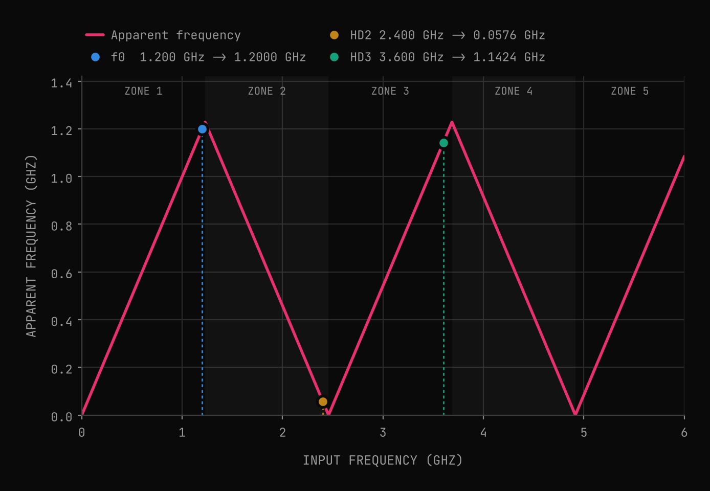
Here is the physics that makes this matter. A converter sampling at cannot tell frequencies apart if they differ by a multiple of . Every input, wanted or not, lands somewhere in the first Nyquist zone, from 0 to :
is the input frequency, the sample rate. Inputs in even Nyquist zones also arrive spectrally inverted.
RF sampling converters turn this from a hazard into a feature: you deliberately place a band in the second or third Nyquist zone and let the sampling do the downconversion. The theory of where that is legal, and how much guard band it needs, is laid out cleanly in Vaughan et al. 1991. The catch is that the converter applies the same folding to everything, including the harmonics your own front end produces.
A harmonic 57.6 MHz from the signal
Take a common RFSoC sample rate, 2.4576 GSPS, and a 1.2 GHz tone inside the first Nyquist zone, just below = 1.2288 GHz. Its second harmonic at 2.4 GHz folds down to 57.6 MHz, which is easy to ignore. Its third harmonic at 3.6 GHz is in the third zone and folds to 1.1424 GHz: 57.6 MHz away from the tone you care about, close enough to sit inside the analysis band of many applications.
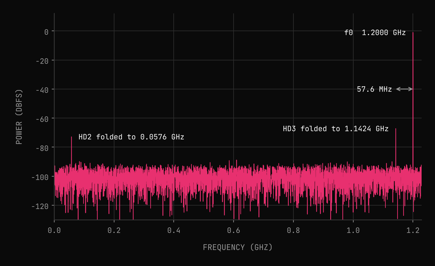
None of this is hard to compute. It is hard to remember to compute, every time, for every channel, while you are also fighting a toolflow. On the bench it would show up as an unexpected spur, and the first suspicion would fall on the FPGA logic, not the frequency plan. That is the gap I wanted closed: the arithmetic exists, but nothing in the workflow did it for you at the moment you made the choice.
The idea
The idea was simple to state. Treat the signal chain as a model rather than a set of settings. Draw it as a graph of blocks. Let sample rate, data type and centre frequency propagate along the edges, so every block knows what it is receiving. Check each block against the real limits of the board it targets. Let me probe any point and see the signal there. Then, when the model is right, hand the configuration to the CASPER toolflow instead of retyping it into a wizard.
- 01Propagate: rates, types and frequencies flow through the chain, so a mistake shows up at the block that causes it.
- 02Check: every block validates against the board's actual converter and fabric limits.
- 03Probe: look at the signal at any point in the chain, in simulation, before any hardware is involved.
- 04Export: the same model produces the toolflow configuration, so what you checked is what you build.
Apexia LLC had been formed in March 2026. On April 7, 2026, the folder of tools became the first commit of a new repository: "existing RF/RFSoC tools". That repository is what Apexia Fabric grew out of.
Next: deciding what not to build
An idea like this can expand forever: simulation, code generation, documentation, installers, multi-board systems. Version 0.1.0 was tagged one day after that first commit, and it did not do most of those things. Chapter 2 is about how the first version was scoped, what it contained, and what was deliberately left out.
See where the itch led.
Apexia Fabric is free to download as a beta and runs entirely in simulation, no hardware required. If you have your own idea that needs a first version, that is what our MVP builds are for.
REFERENCES
- [01]Hickish, J., Abdurashidova, Z., Ali, Z., et al. (2016). A Decade of Developing Radio-Astronomy Instrumentation using CASPER Open-Source Technology. Journal of Astronomical Instrumentation, vol. 5, no. 4, art. 1641001. doi:10.1142/S2251171716410014
- [02]Vaughan, R. G., Scott, N. L., White, D. R. (1991). The theory of bandpass sampling. IEEE Transactions on Signal Processing, vol. 39, no. 9, pp. 1973-1984. doi:10.1109/78.134430
KEEP READING
Related articles.
An MVP You Can Finish: Scoping Fabric v0.1
Chapter 2 of the Apexia founder diary: what the first version of Fabric did, what it left out, and why propagating sample rates tells you the SNR you can expect.
OCT 23, 2026 · 6 MIN READ
Digital Down Conversion (DDC): A Practical Guide
How digital down conversion works: NCO mixing, CIC and FIR decimation, bit growth, aliasing, and when to use the RFSoC's hard DDC blocks instead of fabric.
JUL 25, 2026 · 9 MIN READ