FOUNDER DIARY · CHAPTER 04 / 10
From One Box to a System: Nodes, Links and a Link Budget
Chapter 4 of the Apexia founder diary: the System Architect spec, a Python core of nodes, links and antennas, and the Friis link budget behind it.
- PUBLISHED
- OCTOBER 30, 2026
- READ
- 6 MIN READ
- BY
- THE FOUNDER · APEXIA
Chapter 3 followed the scope work through April 10, 2026. This chapter covers the other large thing that happened that day. The history shows 42 commits on April 10, against one on April 7, three on April 8 and five on April 9. Some of those 42 were the window catalog. Many of the rest were the start of something bigger than a signal chain.
Chapters 1 to 3 were about a signal chain on an RFSoC: its converters and the blocks behind them. On April 10 a design spec called System Architect was written and approved, and the Python core built from it the same day modelled a system of nodes, links and groups, with antennas, timing hardware and coverage. A single board was no longer the whole picture. This chapter is about that turn, and about the first piece of physics any system of separated nodes has to answer: how much signal arrives at the other end.
A spec and three plans in one day
The order of work on April 10 matters more than its volume. First came the System Architect design spec, with its brainstorm notes, written and approved. Then came Plan 1: Python Core, an implementation plan of 14 tasks. Plan 2, a React front end, and Plan 3, a Tauri desktop shell and advanced features, were written the same day. I planned each subsystem in a written spec and an implementation plan before building it, and April 10 is the clearest example of that order in the history.
The reason is scope. A board-level configurator has one natural boundary: the board. A system has no natural boundary at all. You can always add another node, another link type, another kind of estimate. Writing the spec first was how the work got a boundary. Splitting it into a core, a front end and a desktop shell was how the boundary got an order: the models had to exist and be tested before anything drew them. Plans 2 and 3 are the subject of later chapters. This one is about Plan 1.
What the Python core contained
Plan 1 was built on April 10. Read as a list, it is the inventory of what a system model needs before it is useful:
- Core data models with serialization and tests.
- A system architecture model of nodes, links and groups. A link can be fibre, White Rabbit timing, or Ethernet.
- Antenna specs and radiation patterns, with a built-in horn catalog.
- A timing hardware catalog with topology validation and latency computation.
- An antenna coverage engine for cones and baselines.
- A chain-assignment cascade: a setting on a node overrides its group, and a group overrides the global default.
- FPGA resource estimation with the capacities of the ZCU216, RFSoC 4x2 and ZCU111.
- Frequency-plan conflict detection.
- A project file format with save, load and legacy import.
- An aggregate estimator for data rates, storage and backhaul.
- A FastAPI service with project, system, antenna, hardware, chain and frequency endpoints.
Two items on that list say the most about the turn. The chain-assignment cascade is what makes a system manageable: several identical nodes can share one chain definition, with one node overriding it where it differs, rather than separate copies that drift apart. And FPGA resource estimates keyed to the part are what make a system honest: a chain that fits on one RFSoC may not fit on another, and a system tool that ignores that is drawing pictures. The public README still lists that feature today.
The FastAPI service was the other quiet decision. With project, system, antenna, hardware, chain and frequency endpoints behind HTTP from the first day, the core was separate from whatever would draw it.
The first question two nodes ask
Once you think in terms of antennas on separate nodes, the simplest physical question is whether a signal sent from one node arrives at the other above the receiver's noise. That is a link budget, and its core is the transmission formula Friis 1946 published in a short note. Friis wrote it in terms of the effective areas of the two antennas:
Free space, far field, matched polarization and alignment. and are the effective areas of the receiving and transmitting antennas.
Substituting the gain of each antenna, , and taking decibels gives the form used at the bench:
Powers in dBm, gains in dBi. The last term is the free-space path loss.
The path loss grows by 20 dB for every factor of ten in distance. At 5.8 GHz the wavelength is 5.17 cm, so the loss is 47.72 dB at 1 m and 107.72 dB at 1 km. Gain at either end buys it back one decibel at a time.
The other side of the budget is what the receiver can hear. Thermal noise in any conductor at temperature sets a floor that no design removes; Johnson 1928 measured it and showed that its power is proportional to absolute temperature. At 290 K the available noise power density is dBm/Hz, usually rounded to . Integrate over the receiver bandwidth, add the receiver's noise figure and the signal-to-noise ratio the demodulator needs, and you have the sensitivity:
B in hertz. For B = 20 MHz, NF = 6 dB and a required SNR of 10 dB, S = dBm.
With a 20 MHz bandwidth, is 73.01 dB, so the thermal floor is dBm. Adding a 6 dB noise figure and a 10 dB required SNR puts the sensitivity at dBm. The figure puts both sides on one plot: received power against distance for two pairs of horns at 5.8 GHz, with 10 dBm into the transmitting antenna.
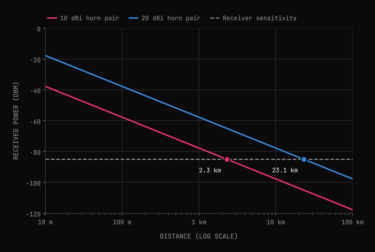
The 10 dBi pair reaches the sensitivity line at 2.31 km. The 20 dBi pair reaches it at 23.10 km. The ratio is exactly 10: the second pair has 10 dB more gain at each end, 20 dB in total, and 20 dB is one decade of distance on a 20 dB per decade slope. At 1 km the 10 dBi pair has 7.27 dB of margin and the 20 dBi pair has 27.27 dB.
Those numbers are the idealized case. They assume a clear line of sight, the far field of both antennas, matched polarization and boresight alignment. Cable loss, pointing error, atmospheric loss and fade margin all come off the top in a real budget. The value of the clean version is that it shows the structure: every term is a decibel added or subtracted, so a change anywhere in the system shows up as a change in range you can predict.
Why the system needed its own model
The link budget is a small example of a larger point. Every term in it belongs to a different part of a system: the transmit power to one node's chain, the antenna gains to the antennas, the distance to where the nodes sit, the bandwidth and noise figure to the other node's chain. No single board owns that calculation; it lives between them.
The same is true of the other models in Plan 1. Timing latency depends on the topology between nodes, not on any one node. A frequency-plan conflict is two chains sharing spectrum they should not. Aggregate data rate, storage and backhaul are sums over every node. Coverage is a property of where antennas point and how far apart they sit. Each one is a question about relationships, and relationships need a model in which nodes, links and groups are first-class objects. That is what April 10 added.
Next: throwing away the first UI
The first UI was PyQt, and it worked. Chapter 5 covers the new front end scaffolded the same day, April 10, and how the PyQt UI was retired eight days later. You can try the current system architect in Apexia Fabric in simulation today, and if you need a system like this designed end to end, our engineering services cover it.
Model the whole system, not just the board.
Apexia Fabric is free to download as a beta and runs entirely in simulation, with no hardware attached. If you have an idea that needs a first version you can finish, that is what our MVP builds are for.
REFERENCES
- [01]Friis, H. T. (1946). A Note on a Simple Transmission Formula. Proceedings of the IRE, vol. 34, no. 5, pp. 254-256. doi:10.1109/JRPROC.1946.234568
- [02]Johnson, J. B. (1928). Thermal Agitation of Electricity in Conductors. Physical Review, vol. 32, no. 1, pp. 97-109. doi:10.1103/PhysRev.32.97
KEEP READING
Related articles.
The Probe Changes the Question: Scope Views and One Window Catalog
Chapter 3 of the Apexia founder diary: Fabric's scope views, why every view shares one window catalog, and what leakage, scalloping and ENBW do to a reading.
OCT 27, 2026 · 5 MIN READ
An MVP You Can Finish: Scoping Fabric v0.1
Chapter 2 of the Apexia founder diary: what the first version of Fabric did, what it left out, and why propagating sample rates tells you the SNR you can expect.
OCT 23, 2026 · 6 MIN READ